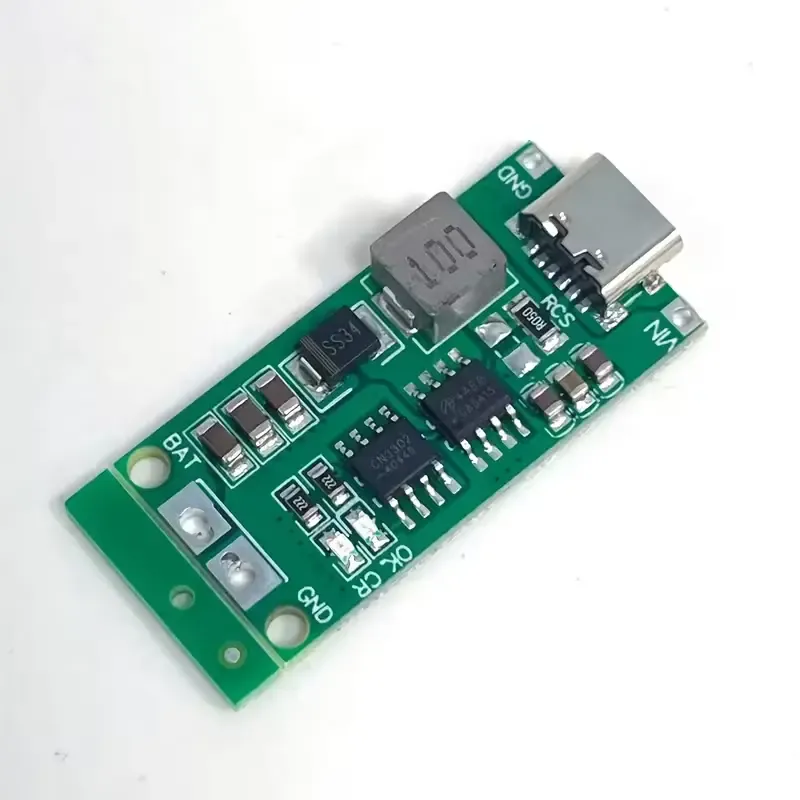
2S 2A Li-ion Battery Protection & Boost Charging Board For 18650 Batteries - Type C
Share
R60.00
Buy and save
Buy and earn R0.34 Loyalty for your next purchase
Loyalty is a discount program that lets you buy products and earn points to redeem on your next purchase. Your Loyalty balance is updated when you pay online or in-store. The Loyalty amount shown on this page can be recalculated at the checkout.
In stock
1
2S 2A Li-ion Battery Protection & Boost Charging Board For 18650 Batteries - Type C
Share
Product Details
| Spec | Value |
|---|---|
| Component Type | 2S Li-ion battery protection board + boost charger module |
| Input | USB Type-C, 5V (charging input) |
| Output Voltage | 3–6V adjustable boost output |
| Battery Configuration | 2 Series (2S), e.g. 2x 18650 3.7V cells (8.4V pack) |
| Charge Voltage | 8.4V (full charge, 2S pack) |
| Key IC | Dedicated Li-ion charge/protection controller + boost converter IC |
| Protection Features | Overcharge, over-discharge, overcurrent (OC/CR test pads) |
| Interface / Pinout | BM+ (battery positive), GND, OK/CR (protection test points), OUT+/OUT− (boost output), USB-C (charge in) |
| Indicators | Onboard LED(s) for charge status (varies by unit) |
| Mounting | Through-hole pads, no mounting holes (hand-solder or wire-tap) |
| Compatible With | Arduino, ESP32, Raspberry Pi, and other 3–6V powered projects |
| Typical Use | Portable USB-C rechargeable 2x 18650 power packs, small robotics, handheld devices |
Handy Tips
Wire polarity before power-up — Double-check BM+ and GND against your cell pack before connecting; reversed leads can destroy the protection IC instantly, and there's usually no reverse-polarity fuse on boards this cheap. Solder a small paper label on the pack noting + and − if you disconnect and reconnect often.
Match your cell chemistry — This board is tuned for 2S Li-ion/Li-poly (3.7V nominal, 4.2V full charge each cell = 8.4V pack). Don't substitute NiMH or LiFePO4 cells without checking the charge-termination voltage, or you'll either undercharge or damage the cells.
Balance the cells manually first — Cheap 2S protection boards like this typically protect the pack as a whole, not each cell individually. If your two 18650s have noticeably different capacities or ages, charge them separately to equal voltage before wiring them in series, otherwise one cell will drift and degrade faster.
Mind the boost output current limit — The onboard boost converter (small inductor visible near the USB-C port) is usually only good for 1–2A continuous; check the datasheet or test with a multimeter under load before powering anything current-hungry like motors.
Don't rely on OK/CR pads as a fuse — Those test points are for verifying protection circuit function, not a substitute for a physical fuse or PTC. Add an inline fuse if this board feeds a project where a short circuit is a real risk (e.g., exposed wiring).
Check output voltage before connecting a load — These boards sometimes have a trimpot or fixed-voltage strap; measure OUT+/OUT− with a multimeter first, since feeding 6V into a 3.3V-only device (like a bare ESP32 without its own regulator) will fry it.
Ventilate during charging — The boost IC and charge controller can get warm under sustained load; avoid enclosing the board in a sealed case without airflow, especially if you're charging and discharging simultaneously (pass-through use).
Display prices in:ZAR