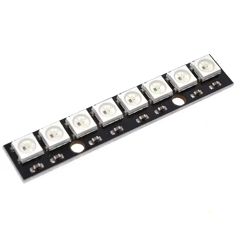
WS2812 8-ch RGB LED driver
Share
R33.91
Buy and save
Buy and earn R0.19 Loyalty for your next purchase
Loyalty is a discount program that lets you buy products and earn points to redeem on your next purchase. Your Loyalty balance is updated when you pay online or in-store. The Loyalty amount shown on this page can be recalculated at the checkout.
In stock
1
WS2812 8-ch RGB LED driver
Share
Product Details
WS2812 8-Channel RGB LED Driver Module
| Spec | Value |
|---|---|
| Driver IC | WS2812 (integrated LED + driver, or WS2812B breakout with 8 channels) |
| LED Type | Individually addressable RGB (WS2812/WS2812B) |
| Channels | 8 (8 independently controllable RGB LED outputs/pixels) |
| Operating Voltage | 5V DC |
| Data Interface | Single-wire digital (NZR communication protocol) |
| Color Depth | 24-bit (8-bit per R, G, B channel) |
| Control Signal | 800kHz single-wire data, cascadable (DIN/DOUT chaining) |
| Current Draw | Up to ~60mA per LED at full white brightness (plan power budget accordingly) |
| Interface | VCC, GND, DIN (and DOUT for daisy-chaining additional modules) |
| Compatible With | Arduino, ESP32, Raspberry Pi (via FastLED, Adafruit NeoPixel, or similar libraries) |
| Typical Use | Addressable LED strips/rings, status indicators, ambient lighting, small LED matrix/pixel arrays |
Handy Tips
Only one data pin controls all 8 channels — Unlike simple RGB LEDs needing 3+ PWM pins each, the WS2812's single-wire protocol lets you control all 8 (or hundreds) of LEDs from a single microcontroller GPIO pin, since color data is shifted through each LED in sequence.
Timing is critical — The WS2812 protocol requires precise microsecond-level pulse timing to distinguish a "0" bit from a "1" bit. Use a dedicated library (FastLED, Adafruit NeoPixel) rather than bit-banging manually, especially on multitasking platforms like ESP32 where interrupts can disrupt timing and cause flickering or corrupted colors.
Add a level shifter if running the MCU at 3.3V — Boards like ESP32 output 3.3V logic, but WS2812 expects a ~3.5V+ data signal when powered from 5V. It often works marginally without one, but a simple logic-level shifter (or a 74HCT125 buffer) on the DIN line significantly improves reliability, especially over longer wires.
Budget your power supply for worst case — At full brightness/white, each LED can draw up to ~60mA. For 8 channels that's up to ~480mA just for the driver module; if you're chaining more LEDs downstream, calculate total current needs rather than powering everything off the microcontroller's 5V regulator.
Add a decoupling capacitor and resistor — A ~1000µF capacitor across VCC/GND near the first LED smooths inrush current spikes, and a ~300-500Ω resistor in series on the DIN line reduces reflections/ringing on the data line — both commonly recommended to prevent the first LED in the chain from being damaged or corrupting data.
DIN/DOUT direction matters — Data flows in one direction only (DIN in, DOUT out to the next device). Double-check the arrow/marking on the module before wiring a chain, since connecting backwards means the data signal won't propagate.
Display prices in:ZAR